Gaston's Smart Home (GHome)
Join me on my adventure to hack my home. I am not a fan of the commercial, closed source, proprietary home automation systems on the market, so I am building/designing my own from scratch, starting with a smart sprinkler system.
Sprinkler Automation
Automating my sprinkler system is the first project for my home automation system. This is currently a work in progress.
Parts and Tools
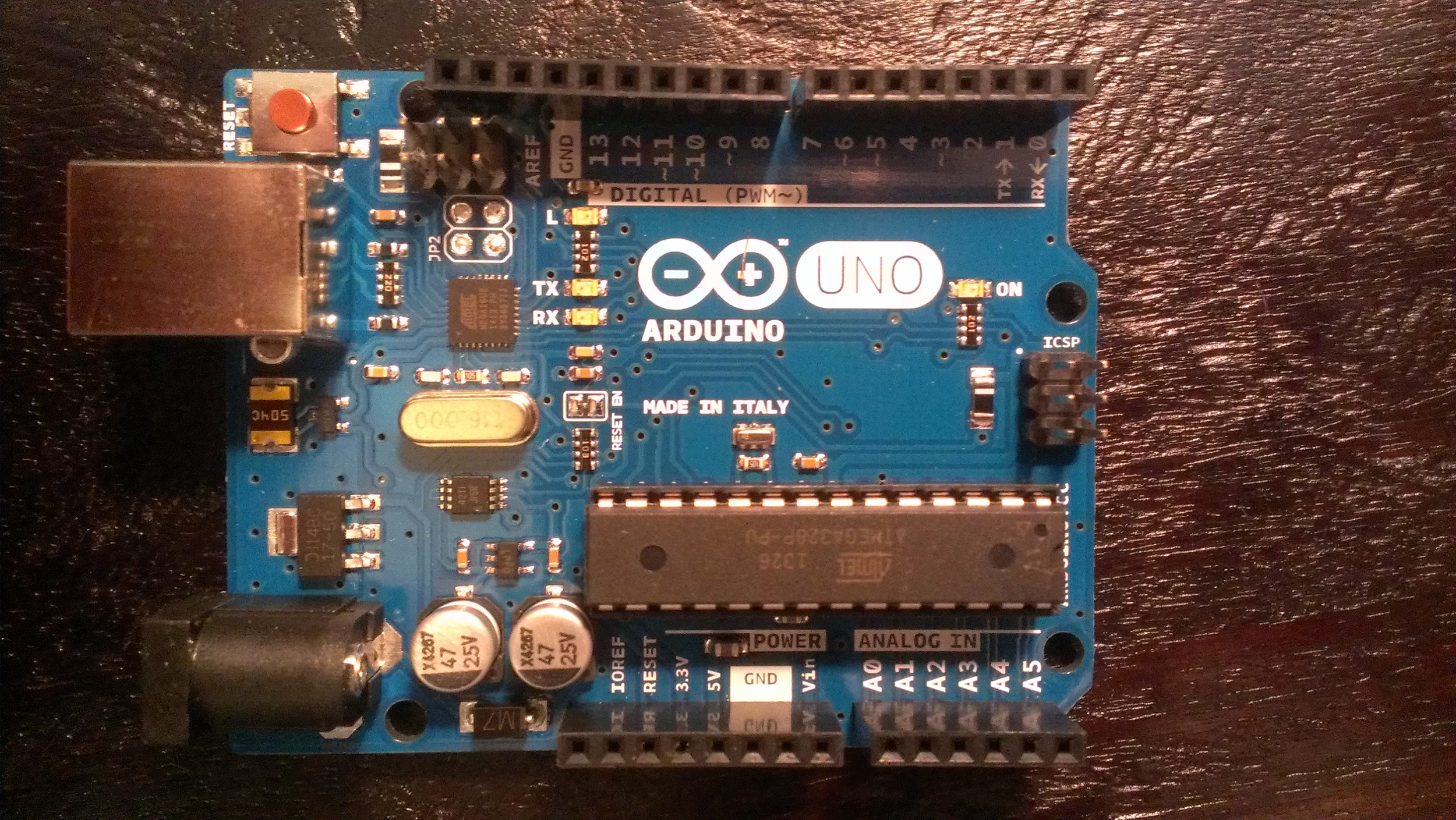
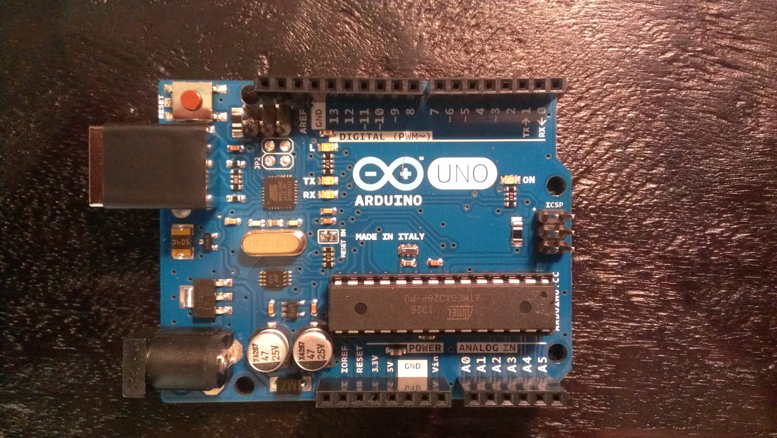
- (1) Ardunio Uno (rev3) - $34.99 (Radio Shack)
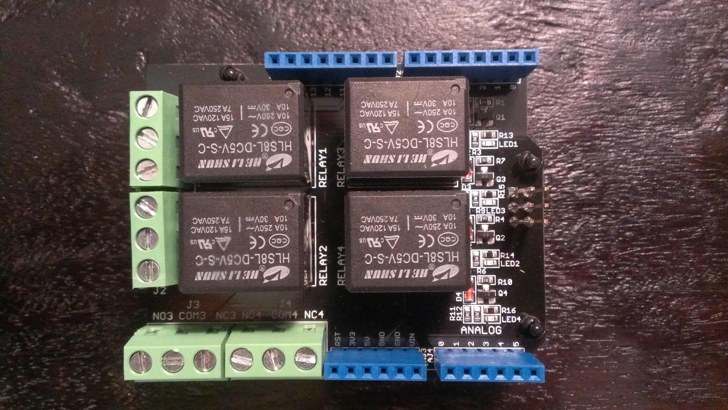
- (1) Seeed Relay Shield - $19.00 (Radio Shack)
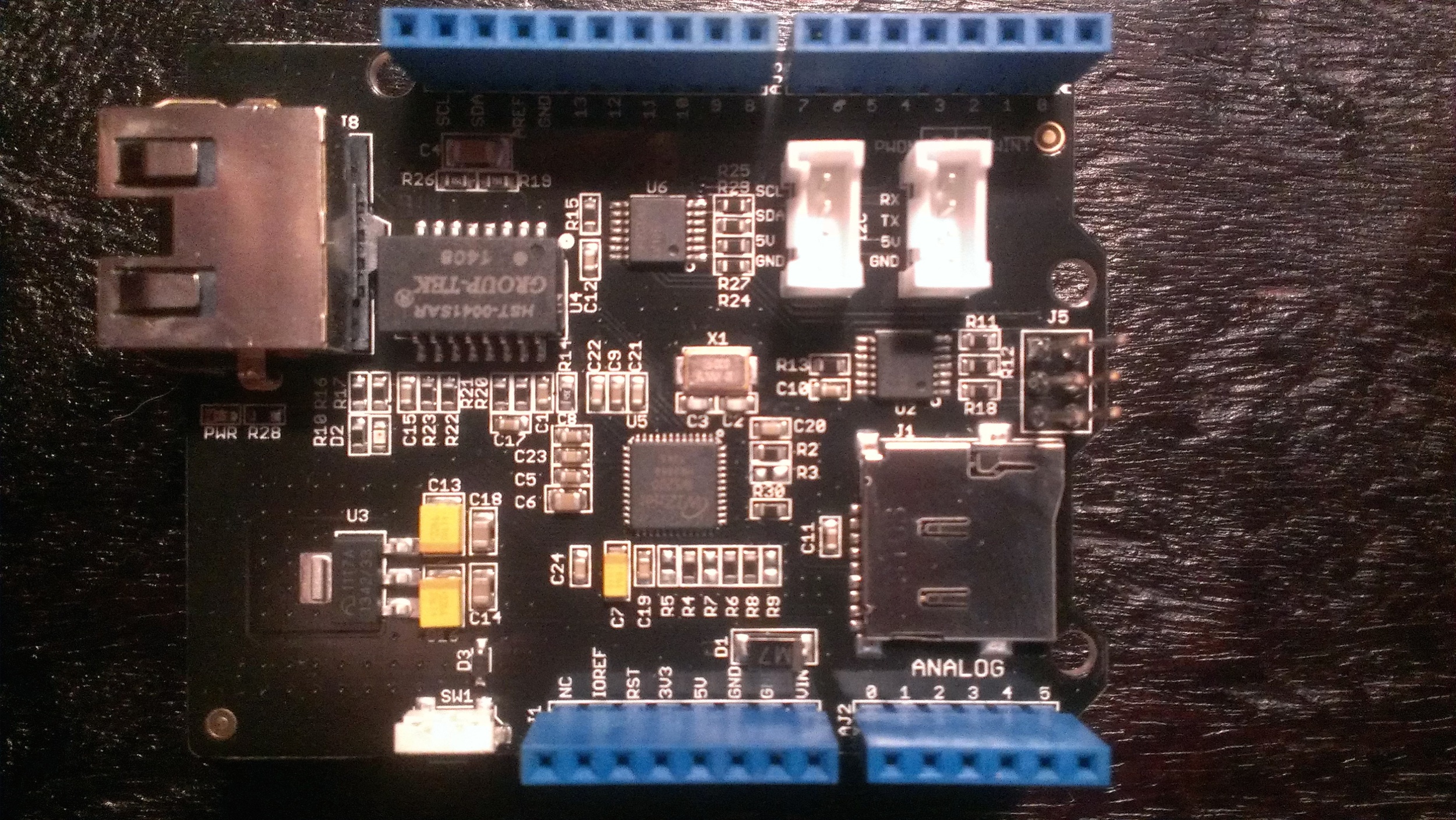
- (1) Seeed Ethernet Shield V2.0 - $31.99 (Radio Shack)
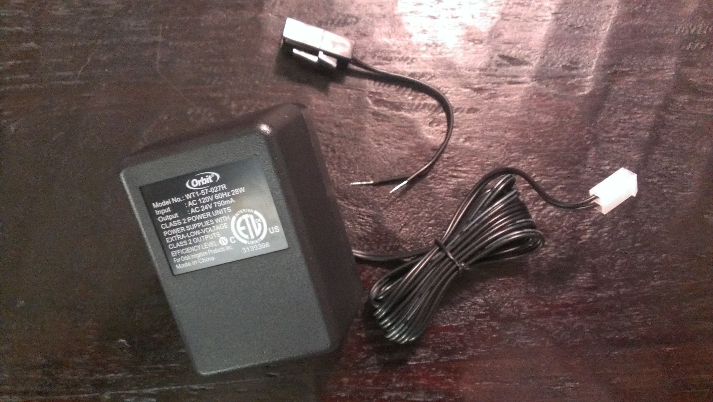
- (1) Orbit 120V to 24V Transformer - $14.96 (Lowes)
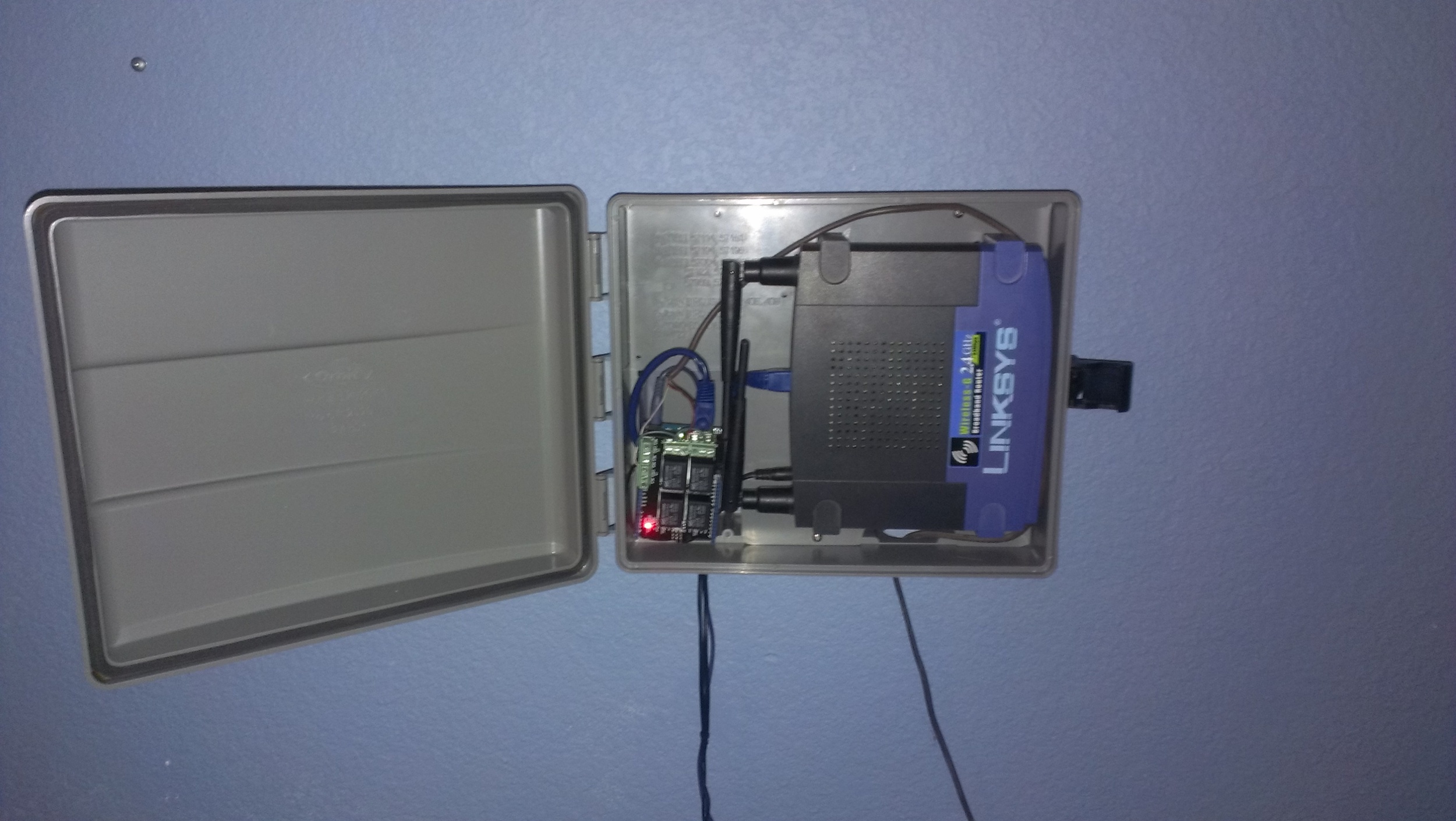
- (1) Orbit Outdoor Timer Box - $29.97 (Home Depot)
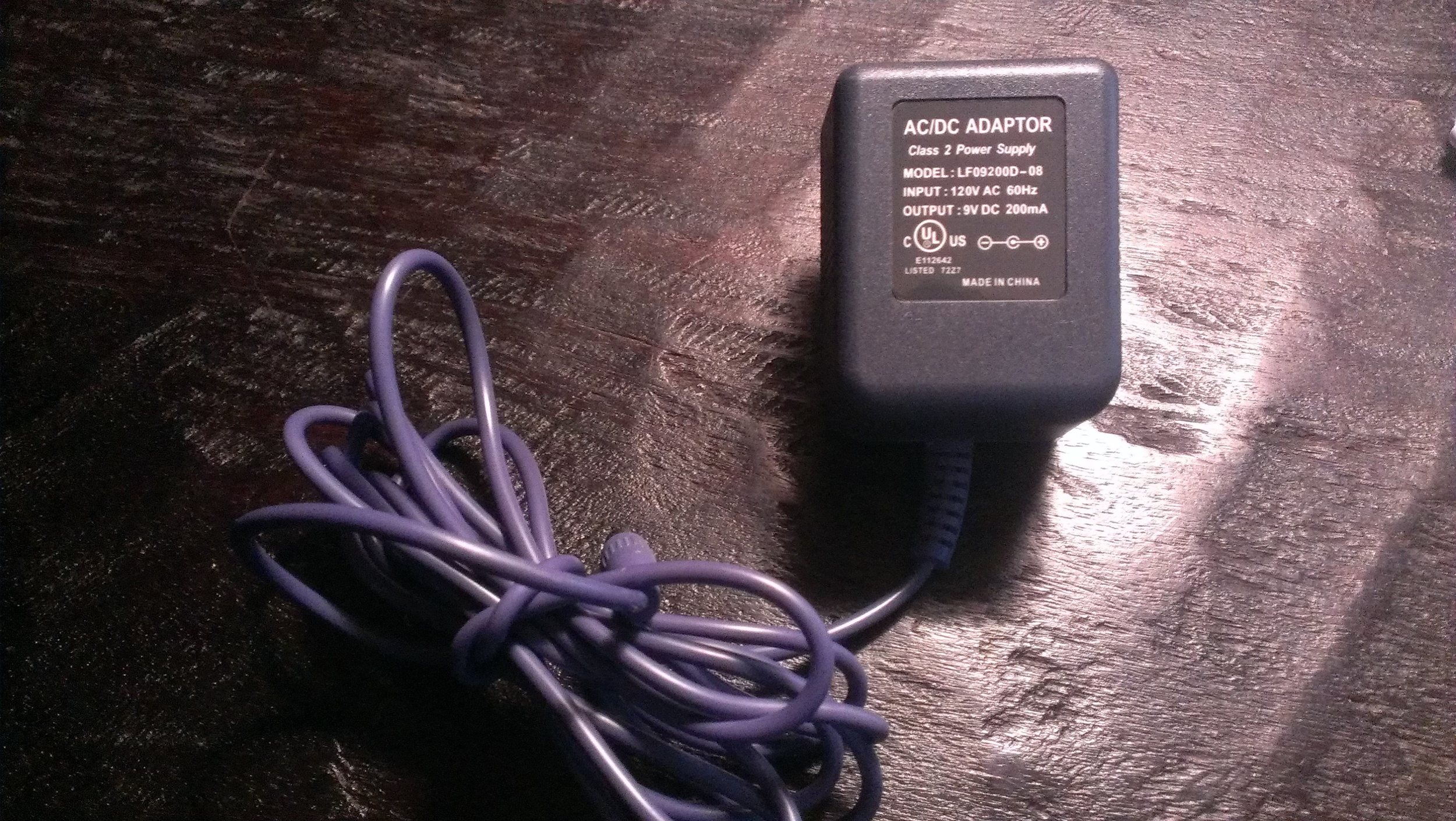
- (1) 9V DC Adapter - (Repurposed from an old wireless bluetooth mouse power supply)
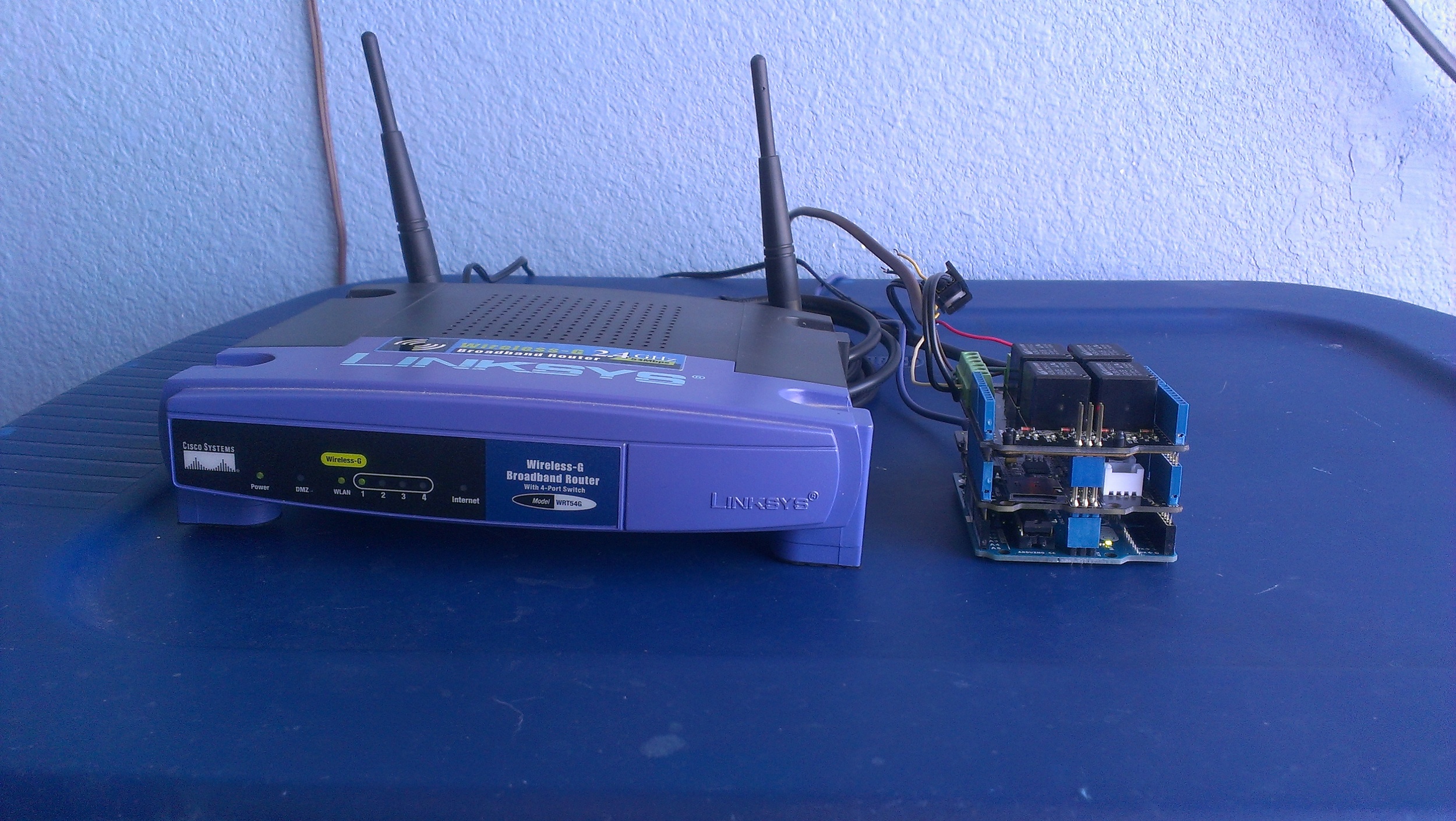
- (1) Linksys WRT54G Router - (I already had this classic device in the closet)
- (1) 1-ft Cat 5e Patch Ethernet Cable - $2.98 (Home Depot)
- (1) Power strip and extension cord
- Electrical tape
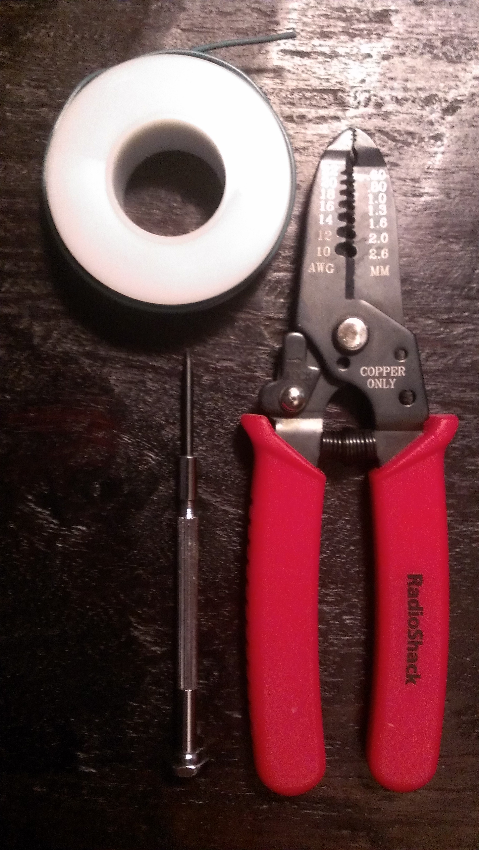
- 22 gauge wire
- Tools: wire stripper, small flathead screwdriver, drill
Sketches
The Sketches below are iterative progressions as I work through the build.
Day #1 [gsprinkler.ino] - Initial POC. Alternates turning zone 1 and 2 off and on for 30 seconds.
Day #2 [gsprinkler2.ino] - Added support for a simple web server. This version was based on the Arduino WebServer example (Examples > Ethernet > WebServer). My version includes a JSON response and minimal support for toggling zones on and off. Sending a request to http://192.168.1.40 returns the status of each zone, and passing toggle=<zoneNumber> as a request parameter toggles the state of the relay for the given zone. For example, http://192.168.1.50/?toggle=1 turns on the sprinkler for zone 1 (assuming it was previously off).
1) Upper left - Ardunio 'gsprinkler2.ino' sketch, 2) Upper right - JSON response from embedded web server, 3) Bottom left - ping to Arduino, 4) Bottom right - Serial console for debugging HTTP requests
Prerequisites
- Configure a secondary router to run in client bridge mode. This basically turns an old router into a wireless client. You can then plug in your Arduino's ethernet port to the router. I am not a big fan off running long ethernet cables from my office to the garage. I had an old Linksys WRT54G router that I flashed with DD-WRT and then followed these instructions.
- Download and install the Seeed Ethernet library.
- Upload the latest sketch from my GitHub project.
Assembly
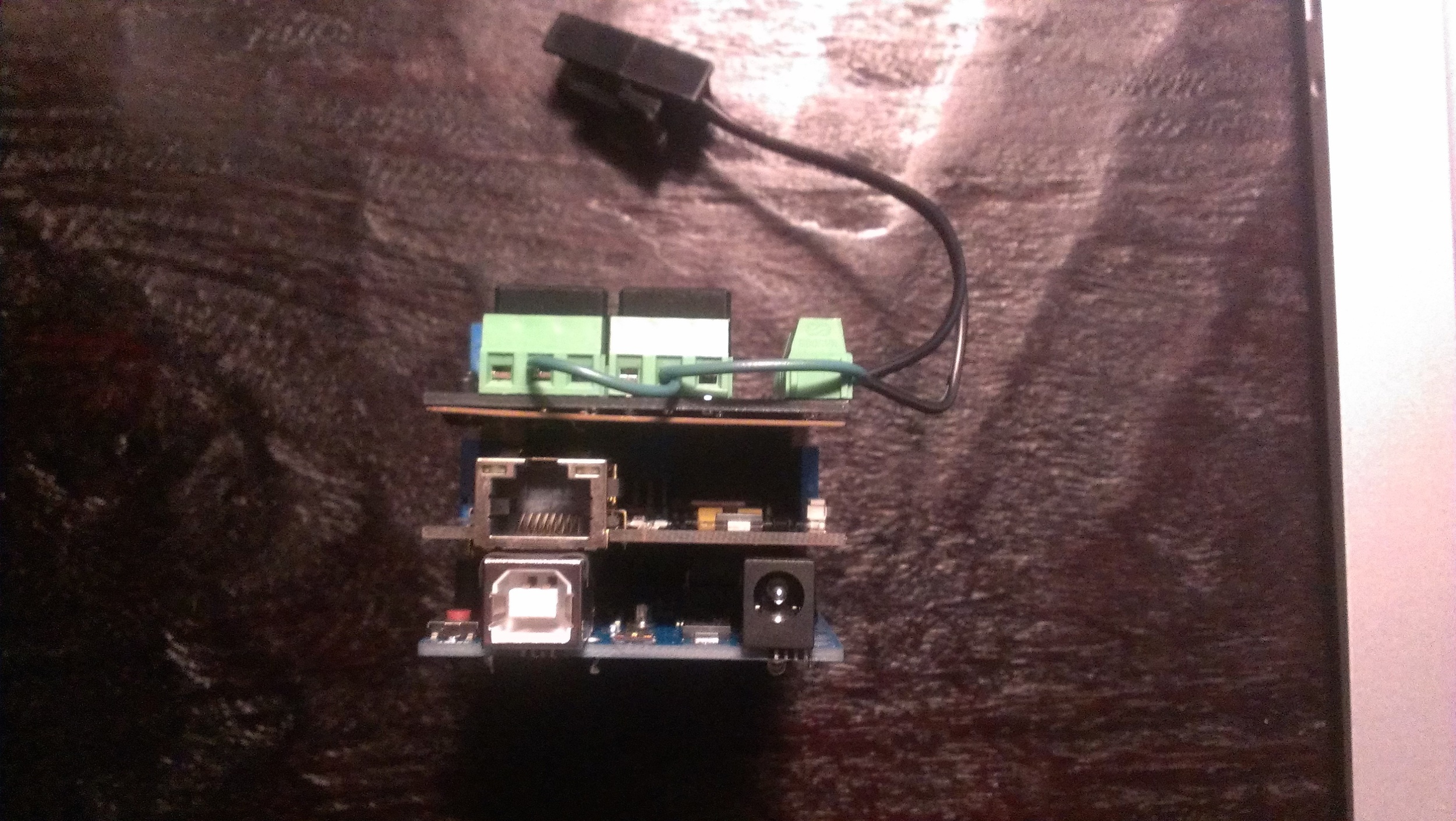
- Cover the USB connector with electrical tape to prevent the shield from making contact with the Arduino.
- Place the Seeed Ethernet Shield on the Arduino.
- Place the Seeed Relay Shield on the Seeed Ethernet Shield.
- Wire the positive 24V wire to the common (COM) pins and wire each sprinkler zone to a normally open (NO) relay. I only have two zones, so I only wired the J1 (COM1/NO1) and J2 (COM2/NO2) interfaces.
- Wire the neutral 24V wire and ground from the sprinkler to an unused relay (NOX). I used the J4 interface (NO4).
- Connect an ethernet cable to the Seeed Ethernet Shield and to port 1 on the router. Actually, in port will work with the exception of the WAN port.
- Connect the 9V DC adapter to the Arduino. This will provide enough power to power to all three (3) boards. The Arduino power adapter page indicates that you need at least 250mA current output, however, mine is only 200mA and it appears to work fine.
- Connect the 9V DC adapter and 24V transformer to an outlet.
- Once everything is powered on, hit the reset button on the Arduino otherwise the ethernet will never initialize this. This is a known problem.
- Test and mount everything in the enclosure.

Linux Control Server
For my home automation server I decided to go with an old Asus Eee PC. This machine is perfect for the following reasons:
- I already had this device.
- It has a small form factor and is fairly quite.
- Since it is a netbook, I get a system with a battery backup system for "free."
- The server needed for this setup requires very little horse power.
Hardware Specs (Asus Eee PC 1005-HAB)
- CPU: (1) Intel Atom N270 @ 1.6 GHz
- RAM: 1 GB DDR2 SDRAM
- HD: 150 GB
- Wireless: 802.11b/g/n (draft)
- Network Interface: 10/100 Ethernet
- USB: (3) USB 2.0
- Resolution: 1024 x 600 (WSVGA)
Operating System
I decided to go with the minimal install of CentOS 6.6. I chose CentOS since I am a long-time Red Hat user (since the 5.2 days) and typically work with RHEL and CentOS servers in my day job. The minimal install is perfect as I don't need X Window and really need a server install. The Asus Eee PC boots nicely off a USB thumbdrive. I created the bootable USB using my Mac by following these instructions. Although these instructions are from the Ubuntu site, they work with any .iso image.
Post Installation Configuration
Network Configuration
I decided to use the wired network adapter and assigned it a static IP as follows:
Enable networking and define our gateway. Edit '/etc/sysconfig/network'
NETWORKING=yes HOSTNAME=ghome.gastongonzalez.com GATEWAY=192.168.1.1
Configure the wired ethernet adapter with a static IP. Edit '/etc/sysconfig/network-scripts/ifcfg-eth0'
DEVICE=eth0 BOOTPROTO=none NETWORK=192.168.1.0 NETMASK=255.255.255.0 IPADDR=192.168.1.43 TYPE=Ethernet ONBOOT=yes USERCTL=no
Restart networking.
$ sudo service network restart
Remote Access
I prefer to manage this server remotely via SSH as the keyboard is incredibly tiny. By default, the SSH daemon is enabled and the relevant iptables rules allow remote access to port 22.
I will likely disble root login access, shortly. The only modification I made was to enable a login banner. I defined a banner using ASCII art in '/etc/issue.net' and added
Banner /etc/issue.netto '/etc/ssh/sshd_config' and restarted SSH.

SSH login banner
Controller Server Architecture
Given that I spend most of my professional day working on backend Java technologies, I decided to use this project as an opportunity to keep my front-end skills current. As such, I opted for a Single Page Application architecture based on JavaScript, HTML5 and CSS3.
- Web Tier - Varnish
- Application Tier
- Server-Side
- Node.js - Server-side JavaScript
- http://expressjs.com/ - Application framework for REST-based services
- Client-Side
- Server-Side
- Data Tier
- MongoDB - Document store / persistence layer
- Mobile
- Web Browser
- Apache Cordova
Web Tier - Varnish
Not yet implemented. However, Varnish will function mostly as an HTTP proxy to Node.js.
Application Tier
Node.js provides a simple web server and hosts the REST-based APIs. The client application is a Single Page Application built on AngularJS and Bootstrap.
Data Tier
Not yet implemented.
Mobile
Not yet implemented; however, the Sinlge Page Application works perfectly on mobile.
Single Page Application


TODO
- Day 1 - November 15, 2014
- [x] Buy parts
- [x] Arduino development 101
- [x] Assemble components
- [x] Perform proof-of-concept
- [x] Create home automation page (this page)
- Day 2 - November 16, 2014
- [x] Add support for Seeed Ethernet shield
- [x] Setup Linksys WRT54G
- [x] Flash with DD-WRT firmware
- [x] Configure bridge networking mode
- [x] Update sketch to support networking and accept remote requests
- [x] Mount components in an enclosure
- Day 3 - November 19, 2014
- [X] Repurpose Asus Eee PC as a Linux controller server
- [X] Install and secure CentOS 6
- Day 4 - November 22, 2014
- [x] Design Controller Server
- [x] Learn Node.js and AngularJS
- [x] Replace 9VDC 200ma adapter with 9VDC 1000ma adapter. The former was not providing sufficient power to all three boards.
- Day 5 - November 23, 2014
- [x] Implement initial Node.js server with sprinkler support
- Day Unplanned
- Design Android / iOS application
- Apache Cordova
- Native
- Add more features
- Add support for security. Currently, anyone on the LAN can control the sprinkler system.
- ???
- Design Android / iOS application